Posts

Cisco 28XX, 38XX series Access Points issue with SG3XX, SF3XX or similar switches.

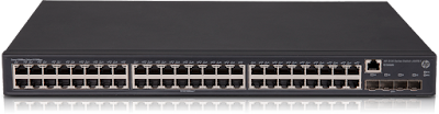
Few cases are there that, the new Cisco Aps are able to power on through POE but the SSID is not broadcasted. The reason for this is insufficient power output from the switch. Coming to the basics a PoE switch will support a maximum of 15.4W and a PoE+ switch will support a maximum of 30W. So, In order to get this done, you should must have a PoE+ Switch at the first place, as the power requirement for new cisco switches is 30W. But, if even though having a PoE+ switch, you are facing issue? then configuration is the place where you need to head. By default the switches comes with a maximum output of 15W per port. You need to modify this setting to provide 30W as the maximum per port. To configure this, you can find the settings in the GUI of the switch, port configuration. Or you can do the same configuration via CLI: SG300-28MP(config)#int range gi22 SG300-28MP(config-if-range)#power inline maximum 30000

Configuring SX20 as a Standalone device

Image
Things get much simpler and easy when you want to configure SX20 as a Standalone device. This is a much needed feature when someone wants to use SX20 for Video conferencing but they don't have any telepresence equipment. Using H323 protocol we can configure SX20 as standalone device, where as SIP can be used in case of CUCM deployed environments. To configure SX20 as a standalone device, follow the below steps: 1. Enable H323 from network service 2. Select default call control protocol as H323 3. Select Mode to Off (Optional) 4. Go to H323 configuration page; System -- Configuration -- H323  5. Select Call setup mode: Direct 6. Port Allocation: Static 7. Under H323 Alias, Configure ID as Your SX20 Unit IP address.     Do not assign any URI under ID, leave it with just the IP address. URI will be configured only for       SIP, whereas H323 will work based on IP address only.    (Private or Public IP is immaterial, just assign whatever th...

Cisco Collaboration Meeting Rooms

Image
Cisco collaboration meeting rooms is a cloud based conferencing technology offered by Cisco. CMR is basically a combination of Cisco's Webex and Spark. Webex is basically for initiating conferences through web, presentation sharing and online audio&Video calling. Whereas, Spark is a messaging client just like jabber. Through CMR, One can initiate an online web conference through any browser, any Cisco room based end points, android phones, desktop clients can join to the cmr conference. In order for an end point to join in the conference, any Room based end point must be registered to spark cloud. To register with spark cloud a unique 16 digit pin generated by cisco's partner is mandatory. Below is the video which shows how to add any room based end point to the spark cloud. Once the device is registered on spark cloud, it is good to join in the CMR.

Step by Step guide for integrating CUCM with Conductor

Integrating cisco CUCM with Telepresence conductor What is Ad-hoc conferencing?                 Creating conference by pressing conference button, merge, join on the end point is called as ad-hoc conferencing. Rendezvous conferencing?                 A rendezvous conferencing is when dialing a conference bridge number directly by all the endpoints instead one adding other to conference. In ad-hoc conferencing: They use both xml rpc messaging. The destination for these sip and xml rpc messaging (to conductor) is configured by configuring a bridge number in the unified cm. This bridge number is then assigned to media resource group, and then media resource group is assigned to media resource group list and then finally this MRGL is assigned to a Device. In Rendezvous conferencing: For rendezvous conferencin...

FLEXDSPRM-3-TDM_CONNECT: failed to connect voice-port (1/1/0) to dsp_channel(1/1/3)

Cisco CME DSP Issue If you are running through any of the following error, then this post is for you.  Applicable to Fxo, Fxs ports and PRI E1/T1 ports deployments. 1. Only one way communication is happening 2. Frequently getting the console message:  FLEXDSPRM-3-TDM_CONNECT: failed to connect voice-port (1/1/0) to dsp_channel(1/1/3) 3. Able to call but no audio The reason here, we can call it as a cisco bug or misbehaviour of the router. When there are frequent changes at one side of the PRI trunk or fxs port then router's dsp fails to function properly. Signalling works without any issues though. When this happens you might face one way audio through router. That means if you are having a pri trunk then calls in one direction, pbx --> router or router --> pbx works but not works in the reverse path. Even though if you are calls are working in both the ways, if you see this error, you might experience calls disconnecting in feature. So you should be awa...

Cisco CME with PBX integration

Image
Hello all,            In this, document i will tell you how to successfully integrate Cisco Call manager Express (CME) with any third party PBX with examples. This process is called PRI Trunking or PRI integration.           Recently i was into PRI integration with 3 Cisco routers (Cisco 3945, 2951 and 4130) with IRIS lite PBX.           Integrating a PBX is not a that hard as we think, but it's bit sensitive. Sensitive in the sense while during the PRI integration we just need to be careful while assigning the parameters, they should match at both ends, i.e., on PBX side and CME side as well.           The very first thing to consider for PRI trunking is   "cable".   Yes, the cable which needs to connected between PBX and CME should be a cross over cable. For connecting a cross over cable, at cisco side we should connect to 1,2 4,5. In PBX side we...

SRST configuration CME.

Image
Cisco SRST configuration in CME. Watch the whole configuration from Here Highlighted part is related to SRST. Building configuration... Current configuration : 2179 bytes ! ! Last configuration change at 09:48:23 UTC Wed Sep 21 2016 by pyramid version 15.3 service timestamps debug datetime msec service timestamps log datetime msec no service password-encryption ! hostname Router ! boot-start-marker boot-end-marker ! aqm-register-fnf ! enable password pyramid ! no aaa new-model ! ! ! ! ! ! ! ip cef no ipv6 cef multilink bundle-name authenticated ! ! ! ! ! ! ! voice-card 0 ! ! ! voice service voip  allow-connections h323 to h323  allow-connections h323 to sip  allow-connections sip to h323  allow-connections sip to sip  fax protocol t38 version 0 ls-redundancy 0 hs-redundancy 0 fallback none  sip   registrar server expires max 600 min 60 ! ! voice register global  mode srst  s...

{Solved} Fortinet firewall 5.2.5 and higher SSL portal accessing issue

Recently i have came across the issue that even after making the correct configuration SSL Portal was note opening in Fortigate frimware version 5.2.5 and above. Solution: So in your policies you might have written  Source interface: ssl.root source address: all Destination interface: internal Destination address: all service: all action: accept Here, you should not give source address to all. Your ssl root --> lan policy should look like this Source interface: ssl.root source address: <SSL-VPN-SUBNET> source users: <source users group>     >>>>>> The SSL Users group you have created. Destination interface: internal Destination address: all service: all action: accept If your configuration is correct apart from this, then you should now be able to see the portal.

{Solved} Fortinet firewall 5.2.5 and higher SSL portal accessing issue

Recently i have came across the issue that even after making the correct configuration SSL Portal was note opening in Fortigate frimware version 5.2.5 and above. Solution: So in your policies you might have written  Source interface: ssl.root source address: all Destination interface: internal Destination address: all service: all action: accept Here, you should not give source address to all. Your ssl root --> lan policy should look like this Source interface: ssl.root source address: <SSL-VPN-SUBNET> source users: <source users group>     >>>>>> The SSL Users group you have created. Destination interface: internal Destination address: all service: all action: accept If your configuration is correct apart from this, then you should now be able to see the portal.

Bandwidth restricting/limiting/shaping with sub-interface in Cisco IOS

Image
Bandwidth restricting/limiting/shaping with Sub-Interfaces in Cisco IOS The following port describes on what is bandwidth limiting and how we can configure them with Cisco routers which are configured with Sub-Interfaces. Scenario: Switch0 configure with 3 vlans Router0 configured with 3 sub-interfaces with correct vlan tags. switch <--> router configured as trunk port. Configuration in router:  Creating access lists that matches the LAN networks. access-list 101 permit ip any 192.168.10.0 0.0.0.255 access-list 102 permit ip any 192.168.20.0 0.0.0.255 access-list 103 permit ip any 192.168.30.0 0.0.0.255   Creating class-maps that maps to the LAN networks:   class-map match-all vlan10  match access-group 101 class-map match-all vlan20  match access-group 102 class-map match-all vlan30  match access-group 103 Note: here vlan10, vlan20, vlan30 are the names of the class-maps that we have cre...

Cisco TelePresence Server Installation (TCS)

Image
CISCO TELEPRESENCE SERVER (TCS) INSTALLATION [STEP BY STEP] For complete installation video watch the video ^ Read carefully!! Important things to remember: 1)You will having an .exe file to install TCS. No any ISO file or .OVA file is required. 2)Windows server 2012 Installed. 3)Sql 2012server SP1 Installed. ( Officially it is said that it will support SP1, SP2, SP3) 4)Licenses you should have one release key and options keys. Installation: 1) Install the windows 2012 server.      In Roles and services add Web server, .net 3.5, .net 4.5, asp .net, Window server Backup. 2) Install SQL 2012 server.     Create a DB Instance with name TCS. and all defaults. 3)Now copy the TCS Installer folder to C drive in windows server. 4)Open command prompt with adminstrator rights. 5)Edit license.txt file and add your serial number, release key and option keys in there without any special characters. 6)Now in command prompt go to the installation...

Finding out the Network Address of IP Address

Image
CALCULATING NETWORK ADDRESS OF AN IP ADDRESS: In this Post I will share you a trick to find out, What is the network address of a IP address. In CCNA or JNCIA Exams we get questions like: what is network address of 172.16.12.100/29? what is network address of 192.168.100.100/26? If it's a class-full subnet (/8, /16, /24) we can find it out easily but in case of a subnetted IP address we required some more time to identify the Sub network IP address. Below is a simple 3 steps formula that gives you accurate Sub-network IP address of any given IP: Step-1: Find out how many hosts we get in that subnet:   (Including Network address and Broadcast address) Like, in  192.168.1.0/24 we get 255 Hosts. 192.168.1.0/29  we get 8 Hosts. 192.168.1.0/30  we get 4 Hosts. Below is the chart that explains how many hosts per bit we get: The above Pic represents the 8 Bits in an octet, And no. of hosts per each bit. So, Clearly if we ...

HP Switch Comware firmware Upgradation

Image
      UPGRADING FIRMWARE IN HP SWITCHES In Switch: <system>system-view [system]ftp server enable local-user admin password simple admin authentication-attribute user-role network-admin service-type ftp quit vlan 2 port gigabitethernet 1/0/1 quit interface vlan-interface 2 ip address 192.168.1.1 255.255.255.0 quit save in PC Turn off windows firewall Turn off Any antivirus Turn off windows defender //connect a cable one end to switch 1/0/1 port and other end to your PC. configure static ip address in your PC. IP:192.168.1.10 Mask: 255.255.255.0 Test the connectivity by pinging 192.168.1.1 Open command prompt with administrator rights Type: ftp 192.168.1.1 username: admin password: admin ftp> binary ftp> put filename.ipe wait for 3 min. file will be uploaded to switch. after uploading completed type in the following commands. <system>boot-loader file flash:filename.ipe all main pres...

Converting cisco 1852 AP to controller (Mobility express)

           CONVERTING 1852 AP TO MOBILITY EXPRESS Get your work done easily, watch the video for this process:   CLICK HERE FOR VIDEO Pre requisites: 1.1852 AP 2.Mobilty express image 3.Mobility express update image 4.TFTP server 5.DHCP server Procedure: Step-1: Connect the 1852 AP in network which have DHCP server. Your PC should be in same network and reachability should be there. (between PC and AP) Step-2: Install the ME image  Open the tftp server and start it. Keep the Mobility express image (30MB) in TFTP-Root directory. go to AP console and issue the below commands: logging console disable      //optional prevents from bothering up with console logging messages debug capwap console cli ap-type mobility-express tftp://x.x.x.x/<image>.tar With the above commands, We have downloaded the ME image into the AP. It Will automatically reboots waits until it does!  Wait 10 - 15 M...

Installing and Configuring Fortinet SSL VPN

Procedure for installing and configuring SSL VPN client. 1)Download the installer from Downloads section. 2)Open the installer and follow on screen instructions. (Install VPN only when shown options) 3)Open the VPN Client application and configure the parameters name, Ip address and port number. 4)Then click on close. 5)Enter the User id and Password as: Username: xxxxxxxx password: xxxxxxxxx and hit enter, Click Yes when prompted. ​

[Step by Step] Configuring SSL VPN in Fortinet 5.2.4 and higher

Image
SSL VPN IN FORTINET 5.2.4 or higher Watching is more Fun than reading... Click the link above!!                                                                                          To configure SSL VPN in Any fortinet firewalls having OS 5.2.4 or higher follow this procedure (it might work for lower versions also, i didn't tested :) ) Note: In Fortinet, by default we get SSL_VPN_TUNNEL_ADD for SSL VPN Users., In this tutorial i have configured the remote users subnet as SSL_USERS_Subnet so wherever i have used this group you use your SSL subnet group. 1. Go to User & Device: add a new local user. 2. Go to user groups and a new group for SSL users and add the users created in step 1 in this group. 3.Go to Policy & Object...